
Piegādes termiņš visā Lietuvā: 5-7 darba dienas.
Piegādes cena uz norādīto adresi: 3 eiro


Apraksts
Trumpai apie prekę
Prekė: Grunto šilumokaičio valdiklis GWC. Kategorija: Rekuperacinės vėdinimo sistemos.
- Gamintojas: IB
- Modelis: IB-Tron 3100GHE
NOTE! PLEASE SUGGEST ONLY THE DESCRIPTION IN THE CONTENT OF THE OFFER !
Due to the fact that in the process of productivization Allegro incorrectly combines offers with products, taking into account only a few parameters, please SUGGEST ONLY THE DESCRIPTION IN THE CONTENT OF THE OFFER and not the title of the product, which may be incorrect.
Unfortunately, we have no influence on this and despite providing the correct parameters, Allegro incorrectly combines offers with products.
General news
The IB – Tron 3100GHE controller is an independent microprocessor controller equipped with a large liquid crystal LCD display. The controller is designed to control Ground Heat Exchangers (GWCs) by controlling throttles and valves with actuators or fans.
The IB – Tron 3100GHE series allows you to control passive heating and cooling processes. It intelligently selects the heat/cooling source taking into account three different temperatures.
Professional and intelligent controller for controlling systems where you should choose a source of heat or cold from two different sources while protecting the building from excessive cooling.
Principle of Action:
The controller is designed to control the process of heating and passive cooling of installations equipped with two different heat/cooling sources. A practical example of such a system is the ventilation system equipped with a Ground Heat Exchanger (GWC).
Ground Heat Exchanger is a device designed for ventilation of a building, with the help of which natural renewable energy can be obtained from a small depth of the ground. The idea of the device is based on the fact of existence at a depth of 1 to 4 meters of almost constant ground temperature throughout the year. In our climate zone at this depth the ground temperature is approx. +10°C (+/- 1,5°C). In fact, GWC is situated very shallowly, sometimes even above the ground, in the case of high groundwater. However, thanks to a special design, GWC foundation is simulated at a depth of 5-6m below the surface of the earth.
Passive cooling: Hot outdoor air is drawn through the intake. Then, flowing through the GWC, it releases excess heat energy into the cool ground - thereby cooling down. The pre-cooled air is directed to the ventilation unit, which can subject it to another heat treatment or direct it to the rooms.
Passive heating: The principle of operation is exactly the opposite of its operation with passive cooling. The cold air flowing through GWC warms up from the warmer ground.
At different times, the outside temperature is more favorable than after passing through GWC. E.g. During a warm and sunny winter day, the outside temperature is higher than after passing through GWC or during a summer night, the outside temperature is lower than after passing through GWC. Then the external air should be sent directly to the air handling unit, bypassing GWC.
The GWC described is of tubular, gravel or diaphragm type. The external air is directed to the ventilation unit by GWC or directly by means of air dampers with an actuator, e.g. type IB-Fxxx (available on other offers).
Since in most cases the resistance to the air passing through GWC is much greater than the resistance to the external air drawn directly, it is enough to use only one throttle on the pipe supplying directly to the external air. Opening this throttle will cause air to be drawn directly from the outside. Closure of air intake by GWC.
In situations where the resistance to direct air is as high as the air directed by GWC or the expected resistance is not unambiguous - two dampers operating alternately (one closed, the other open) should be used.
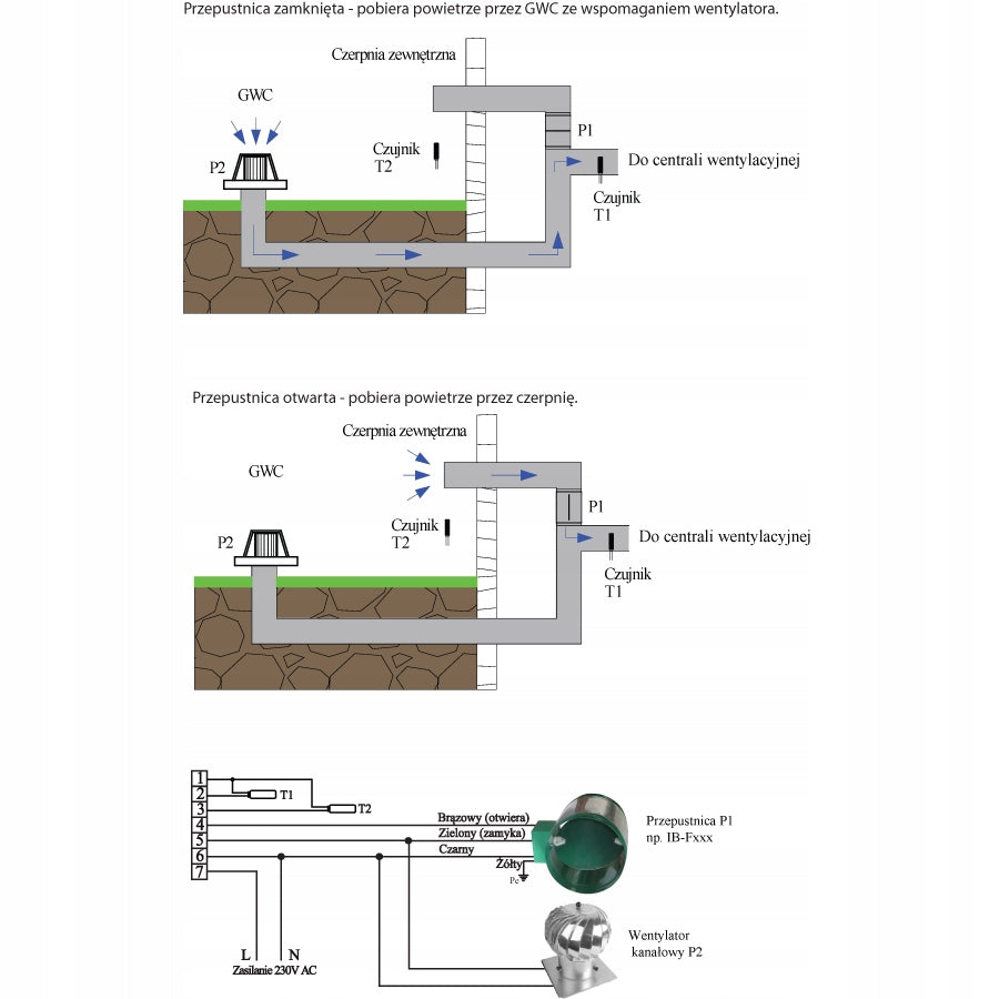
In the event that GWC resistance is significant, it may be necessary to use an additional GWC booster fan.
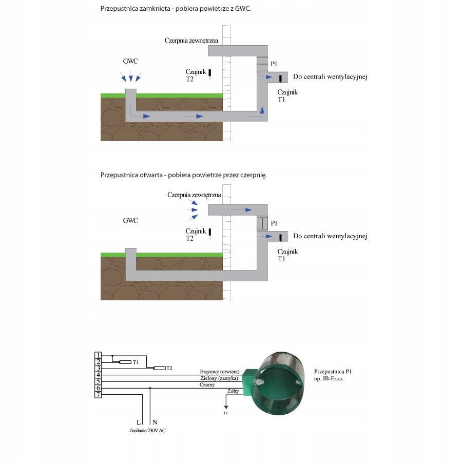
Example Scheme of Operation of Pipe and Gravel GWC:
Example of connection with one air damper:
Example of connection with one air damper and an additional booster fan:
Example of connection with two throttles operating alternately:
Another type of GWC is glycol GWC. Its operation consists in the fact that the air is not directed underground and is not heated / cooled directly and this is done indirectly by an exchanger mounted on the pipe supplying air to the ventilation unit. Cold/heat is received from the lower source which can be the ground through the system of vertical or horizontal pipes buried in it. After switching on the circulating pump, energy is taken away from the ground and put into the air by an appropriate exchanger.
The lower source can also be an efficient deep well, which will work as a source of cold, but will not be an effective source of passive heating.
The IB-Tron 3100GHE controller selects the optimal heat source for cooling and passive heating – it selects whether the air is to pass through GWC or is to be introduced directly from the outside by the appropriate exchanger.
The lower source can also be an efficient deep well, which will work as a source of cold, but will not be an effective source of passive heating.
The logic depends on the current season. The summer and winter seasons can be set permanently or change automatically based on the average outdoor temperature of T2 (if this sensor is connected).
Passive heating is implemented in the winter season – a warmer source is selected.
In the summer season, passive cooling is implemented – a cooler source is selected.
While in the case of the winter season and the implementation of passive heating there is no risk of overheating the room, in the case of the summer season during the implementation of passive cooling there is a real risk of too much cooling of the room. Therefore, the driver allows you to enable appropriate protection.
If the above-mentioned protection option is active and the internal temperature (measured by a built-in temperature sensor), in the summer season it is below the minimum temperature, a warmer source is selected to protect against excessive cooling of the room.
Note: If the protection function against excessive cooling is active, the controller should be installed in a reference room where the prevailing temperature is representative of the entire building. Alternatively, the controller should be placed in a room where too much cooling is burdensome for building users (e.g. bedroom).
The T1 temperature sensor is placed in the duct and indicates the temperature of the input air to the ventilation unit.
Due to the specificity of GWC construction, it is not possible to directly determine the temperature of the input air to the ventilation unit after passing through GWC without its prior commissioning. Therefore, if the currently selected source is intake (external air directly - P1), it is necessary to select the source P2 (start GWC) from time to time for testing purposes to determine what parameters the air will have after passing through GWC (in the case of glycol GWC after switching on the circulation pump). Only after the GWC test work is completed, the T1 temperature is properly measured, which is taken into account when selecting the source.
The time interval of how much GWC test should be performed to determine the correct comparative temperature is defined as the test break P2. GWC test break is expressed in minutes. Its value depends mainly on the type and size of GWC and more precisely on how often thermal conditions in GWC can change. In typical GWC single-family homes, this value is 90 minutes.
The time that determines how long the GWC test is to take place after which the proper measurement of T2 temperature will take place is defined as the test period P2. It is expressed in seconds.
Its value depends on the type and size of GWC, the distance and accuracy of ventilation duct insulation between GWC and the T2 sensor. The P2 test period shall be set empirically or the corresponding calibration function shall be invoked. In typical GWC single-family homes, this value is 120 seconds.
Typically, the second source is intake (direct air supply from the outside). If the T2 sensor is connected, which indicates the external temperature, it is considered as comparative to the selection of the best source.
For optimal operation of the installation in the intake/GWC system, we recommend connecting an external T2 sensor. However, there are cases when connecting the T2 sensor is difficult or unnecessary.
The choice of source is based only on the T1 sensor and the following parameters:
- test break P1;
- the P1 test period;
- test break P2;
- the P2 test period;
The parameters of test break P1 and test period P1 are analogous to those described above related to P2 output (GWC) and concerning P1 output.
If the test period P1 is 0 (default value), it means that the temperature for comparison is taken directly from the T2 sensor. Otherwise, the temperature to be compared is taken only from the T1 sensor after the test work of the P1 and P2 devices.
Note: In order to ensure the correct operation of the controller, the test break should always be greater than the test period for the source.
Note: The P1 test period and the P2 test period are also the minimum time for which a given source must work. This means that after switching the source to P2, the time equal to the P2 test period must elapse in order to change the source to P1.
Examples of Action: T1 and T2 sensor
Typical GWC installation and external intake - direct air extraction from the outside bypassing GWC. A system with one throttle.
- open throttle – air flows from the intake (P1);
- closed throttle - air flows through GWC (P2);
T1 and T2 sensors connected as previously described.
The P1 test period (for intake) is set to 0. The value of the test break P1 (for intake) is irrelevant due to the zero value of the test period P1.
The P2 test period (for GWC) is set to 120 seconds (this is how long the air flow through GWC to the T1 sensor takes). The P2 test interval (for GWC) was set to 90 min.
The current season is summer.
Example of driver operation logic:
- The air is drawn from the outside. The comparative temperature P1 (for intake) is always the current reading T2.
- After 90 minutes, switch to GWC and work for 120 seconds. This period is followed by the temperature from the T1 sensor being remembered as the comparative temperature P2 (for GWC).
- If the comparative temperature P2 is lower than the comparative temperature P1, the source remains P2. If not, switch to P1 (August) again.
- if the air is drawn by GWC, the comparative temperature P2 (for GWC) is the current reading of the temperature T1 if the operating time on GWC has exceeded the value of at least its test period – otherwise this value is adopted since the last valid reading. If the comparative temperature P1 (for intake, the current reading T2) falls below the comparative temperature P2 (for GWC), then the switch to the source P1 (intake) takes place.
- 5. There is a return to point. 1.
Note: If during the operation of the controller it turns out that the internal temperature has fallen below the minimum temperature, which means excessive cooling, a warmer source is selected.
Note: It is possible to switch the source from P1 (intake) to P2 (GWC) before the P2 test break (point 2 of the above-mentioned algorithm). This may be based on the previously remembered comparative temperature P1 (from previous cycles) as this may indicate better parameters of the source P2 (GWC). In order to ensure the correct operation of the controller, the test break should always be greater than the test period for the source.
Examples of Action: Only T2 Sensor
GWC installation and external intake - direct extraction of air from the outside, bypassing GWC. A system with one throttle.
- open throttle – air flows from the intake (P1);
- closed throttle - air flows through GWC (P2);
Only the T1 sensor is connected. The T2 sensor is not connected due to the impossibility of conducting the cable or due to the considerable distance from the intake to the inlet to the ventilation unit (to the T1 measurement site).
Alternatively: A system with two twin GWCs working alternately.
The test period P1 (for intake) is set to 30 seconds (this is how long the air flow from the intake to the T1 sensor takes). The P1 test break (for intake) due to the possibility of frequent change of external conditions was set to 45 minutes.
The P2 test period (for GWC) is set to 120 seconds (this is how long the air flow through GWC to the T1 sensor takes). The P2 test interval (for GWC) was set to 90 min.
The current season is summer.
Example of driver operation logic:
- The air is drawn from the outside. The comparative temperature P1 (for intake) is the current reading T1 if the working time on the intake exceeded the value of at least its test period – otherwise this value is assumed since the last valid reading.
- After 90 minutes, switch to GWC and work for 120 seconds. This period is followed by the temperature from the T1 sensor being remembered as the comparative temperature P2 (for GWC).
- After 90 minutes, the T1 temperature is remembered as the comparative temperature P1 (for intake) and then switched to GWC, which works for 120 seconds. This period is followed by the temperature from the T1 sensor being remembered as the comparative temperature P2 (for GWC)
- If the comparative temperature P2 is lower than the comparative temperature P1, the source remains P2. If not, switch to P1 again (August)
- if the air is drawn by GWC, the comparative temperature P2 (for GWC) is the current reading of the temperature T1 if the operating time on GWC has exceeded the value of at least its test period – otherwise this value is adopted since the last valid reading. If the comparative temperature P1 (for intake, previously remembered in the previous cycle) falls below the comparative temperature P2 (for GWC), then the switch to the source P1 (intake) takes place.
- There is a return to point. 1
Note: If during the operation of the controller it turns out that the internal temperature has fallen below the minimum temperature, which means excessive cooling, a warmer source is selected.
If in the AUTO operating state, damage or exceeding the operating range of the T2 temperature sensor is found and it is also used to measure the external temperature, then the P2 source (GWC) is selected and the test procedures are disabled.
Properties
- Large, blue backlit (optional), liquid crystal LCD display displaying current temperature and other information.
- Blue backlight of the screen (the backlight activates when you press any button and deactivates after some time of inactivity).
- Aesthetic and modern look.
- Easy, intuitive operation and programming.
- Operation based on one, two or three temperatures.
- Implementation of passive heating and cooling.
- Protection against excessive cooling.
- Mains power – no batteries required – with memory and clock support.
- Temperature displayed with an accuracy of 0,1 oc.
- Possibility to calibrate the device (external sensors on long wires, independent calibration T1 and T2). Adjustable hysteresis.
- Test start-up of devices to make a measurement.
- TEST function.
- Keyboard lock.
Scope of delivery
- 1x Thermostat (main panel)
- 1x Power Module
- 1x standard temperature sensor (TSC-8200)
- 1x temperature sensor on silicone cable (TSC-8201)
- 1x This manual
Technical data
- Power Consumption: < 2 W
- Temp. Storage: -5 ÷ 50 ºC
- Temp. displayed: -20 ÷ 100 oc every 0,1ºC
- Setting range: 5 ÷ 90 oc every 0,5 ºC
- Measurement accuracy: 1 ºC
- Hysteresis: 1 ÷ 10 oc every 1 ºC
- Test breaks: 1 ÷ 5999 minutes
- Test period: 0 ÷ 5999 sec.
- Max. load: 2kW per channel
- Power supply: 230V AC
- Housing: ABS
- Display: LCD (3,2'')
- Sizes [mm]: 120x120x23
- Controls: Electronic
- Degree of protection: IP30
- Clock maintenance: 36 months
Construction of the controller
The IB–Tron 3100GHE controller consists of two parts: the main panel with LCD display and keyboard and the relay module.
Both modules are connected to each other using a multi-core cable.
Dimensions
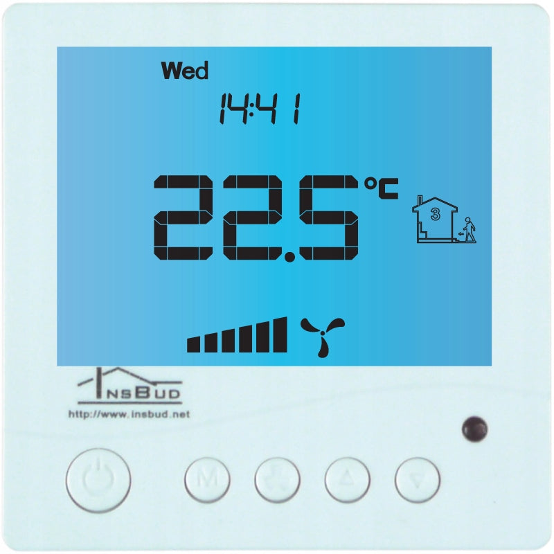
Control panel of the controller
1 - Display
2 - M button
3 - P button
4 - Temperature sensor
5 - UPPER button
6 - DOWN button
7 - FAN/OK button
LCD display
Assembly
Separate the two parts of the main panel housing of the controller. To do this, slide the flat screwdriver into the two slots visible at the bottom of the panel and pry the plastic hooks.
After prying the hooks, carefully separate both halves of the main panel. To avoid damage to the housing, the separation should start from the bottom of the panel (from the side of the hooks).
After separating both parts, disconnect the ribbon wire connecting the main panel to the actuator module by pulling the plug out of the outlet in the front of the panel.
The driver wiring, supplied to the electrical installation box, must be connected to the appropriate controller terminals, according to the instructions. Connection should be made with the power off.
Carefully arrange the excess wires in the electrical installation box, avoiding stresses that can tear the wires out of the terminals.
Place the controller actuator in the electrical installation box and screw the back of the main panel housing with two screws.
Connect the ribbon cable to the outlet in front of the main panel.
Connect both parts of the controller, starting with hooks at the top of the device and ending with hooks at the bottom.
For flush-mounted installation, it is recommended to use a rectangular mounting can with dimensions of 80x80x50mm.
The box is available at a separate auction.
Relay module
- 1, 2 - Between these terminals, turn on the temperature sensor T1 – temperature in the supply duct;
- 1, 3 - Between these terminals, turn on the temperature sensor T2 – outdoor temperature sensor;
- 4 - At this output there is a phase when the source P1 is selected (intake);
- 5 - In this output, a phase appears when the source P2 (GWC) is selected;
- 6 - Neutral cable of the 230V power supply network;
- 7 - Phase cable of the power supply network 230V;
Instructions for use:
Detailed instruction manual in Polish:
http://download.insbud.net/pl/manuals/pl_ib-tron_3100ghe.pdf
Specifications
| Group | Name | Value |
|---|---|---|
| Parametry | Condition | new |
| Parametry | Invoice | With VAT invoice |
| Parametry | Brand | IB |
| Parametry | Kind | switchboard |
| Parametry | Product weight with unit packaging | 0.5 kg |
| Parametry | Manufacturer code | IB-Tron 3100GHE |
| Parametry | Range of energy efficiency classes | A+ - G |
| Parametry | Energy efficiency class | A+ |